Hey everyone, it’s Jake here—you know, the guy who’s been geeking out over silicon steel coils and sheets for the last 12 years, helping everyone from small motor builders to huge transformer plants get exactly what they need. Today, I want to break down something I get asked about every single week: geometric tolerances for these products. If you’re a buyer, a fab engineer, or even just someone curious about why this stuff matters way more than it looks like it does, stick around. This isn’t gonna be the boring textbook stuff—this is real-world, on-the-floor stuff that keeps your projects from crashing and your costs from blowing up. Silicon Steel Coils and Sheets
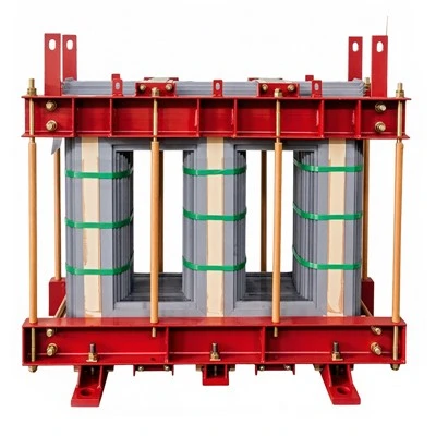
First off, let’s cut the jargon for a sec. Silicon steel (sometimes you’ll hear it called electrical steel, or even “electro-silicon” if you’re chatting with old-timers like me) isn’t just flat metal. It’s specifically made to carry magnetic flux without wasting a ton of energy as heat. But if the shape, thickness, or even how straight the strip is isn’t spot on? All that magnetic goodness goes out the window. That’s where geometric tolerances come in—they’re basically the rulebook that tells us “this product is good enough to work for your application, and this is too wonky to trust.”
Let’s start with the big one everyone cares about: thickness tolerance. This is non-negotiable. For coils, we’re dealing with rolled strips that can be anywhere from a few hundred millimeters wide to super narrow for tiny relays, and thickness usually ranges from 0.15mm to 0.65mm for grain-oriented (GO) silicon steel (the stuff used in big transformers) and 0.35mm to 1.0mm for non-oriented (NO) silicon steel (used in motors, generators, and smaller electrical gadgets). Now, what’s the tolerance? For most standard orders, that’s ±0.02mm, right? Wait, hold on—don’t just take that number and run, because it changes depending on the thickness. If you order a super thin 0.15mm GO coil, we might tighten that up to ±0.015mm because even a 0.01mm difference is a 6% thickness shift, which messes with magnetic properties big time. If you go thicker, like a 1.0mm NO sheet, we can bump it to ±0.03mm, no problem.
But wait, there’s a catch with coils vs. cut sheets. If you have a coil that’s going to be run through a stamping press to make stator cores for an electric car motor, thickness variation across the coil length or width is way worse than a sheet. Let’s say you have a 1m-wide coil—if the thickness shifts by 0.05mm from one edge to the other, when you stamp 10,000 stator cores, half of them will have gaps at the lamination stack, leading to noise and energy loss. That’s why for high-volume stamping coils, we hold thickness variation to ±0.01mm across the entire width. I’ve had customers come to me before saying “my last supplier let 0.04mm variation slide and now my motors are failing quality checks” — that’s exactly why we don’t do that on our premium lines.
Next up: width tolerance. Again, depends on what you’re using it for. For coils, if you’re slitting a wide master coil down to a narrow strip for, say, a transformer’s core limb, width tolerance is usually ±0.1mm. For cut sheets, it’s a bit looser, but not by much—most are ±0.2mm. But here’s a fun fact I learned early on: if your sheet is for a high-frequency inductor, even a 0.5mm overage on a 50mm-wide sheet means you have to trim the edge before assembly, which adds 10% to your waste. On a 10,000-piece order, that’s thousands of dollars wasted. So we adjust width tolerance based on your application, not just a one-size-fits-all spec.
Now, the ones that people don’t think about until it’s too late: flatness and straightness. Flatness is how warped a sheet or coil is. For coils, we measure flatness in “waviness” — like, how much the surface deviates from a perfectly flat plane. For standard industrial use, waviness is kept to less than 1mm over a 1m length. But if you’re using thin 0.15mm sheets for high-precision power electronics, that waviness drops to 0.3mm over 1m. I once had a customer who was using our standard flatness sheets for a medical device’s power transformer. The warped sheets wouldn’t stack evenly, so they had to send back 20 tons of material. Now, they tell us upfront “no warpage” and we bump flatness to 0.2mm over 1m, no extra charge because we know their project can’t handle the extra stress.
Straightness is for uncoiling coils—if a coil is twisted or curved too much, when you feed it through your stamping or punching line, it will “walk” off the roller, jam the machine, or cause uneven cuts. For most coils, straightness is ±2mm per 10m of coil length. For heavy-gauge NO steel (1.0mm and up), we can loosen that a touch to ±3mm because the thicker metal is stiffer, but for thin GO steel, it’s kept to ±1.5mm per 10m to prevent uncoiling headaches. I’ve seen a $50k stamping line down for 8 hours because a coil was too twisted — that’s way more expensive than paying a little extra for a straighter coil.
And let’s not forget edge quality. This is huge for lamination stacks. If the edges of your sheets or slitted coils have burrs, notches, or uneven cuts, when you stack hundreds or thousands of them for a transformer core or motor stator, those burrs create tiny gaps that lead to “stray losses” — basically, energy wasted as heat that makes your unit run hot and lose efficiency. For standard orders, edge burr height is kept to less than 0.05mm. But for high-precision lamination work, we grind the edges to get burrs under 0.02mm. Another thing: cut sheets should have square edges, right? So the angle between the side and end is 90 degrees, within ±0.1 degrees. If it’s off even a little, when you stack the sheets, you get a tapered core that doesn’t fit right, causing vibration and noise. I remember a motor factory that used a supplier with 0.5-degree edge angle tolerance — their motors sounded like tiny vacuum cleaners. Switched to our ±0.1-degree spec, and their noise levels dropped by 15 dB. That’s not a guess — they sent us test results.
Wait, what about coating thickness? Oh right, silicon steel has an insulating coating on it, right? That’s another geometric thing people mix up, but it’s super important. The coating keeps the laminations from shorting each other out when current flows, so it’s not just a protective layer. For most customers, coating thickness is 1-5 microns, with tolerance ±0.5 microns. Too thin, and you get short circuits; too thick, and you add unnecessary thickness to the lamination stack, making your whole unit bulkier. For high-frequency applications, we use a thinner, denser coating with tighter tolerance because extra thickness kills efficiency. I had a customer in solar inverters who was using a coating with ±1 micron tolerance, and their inverters were overheating at high loads. Switched to our ±0.3 micron coated product, and the overheating problem was gone.
Now, let’s talk about how we handle tolerances in real life, not just on paper. We don’t just roll steel and call it good, y’know? We have in-line measuring equipment on every mill and slitter line that checks thickness, width, flatness, and edge quality every single second as the material is moving. For critical orders, we do 100% inspection before it leaves our facility, not just a random sample. We also grade our products by tolerance: our standard grade works for most general motor and transformer parts, our precision grade is for high-volume stamping and sensitive electronics, and our ultra-precision grade is for medical and aerospace applications where every tenth of a millimeter matters.
Wait, I should clear up a common myth here. Some guys think “wider tolerance = cheaper material” — that’s true, but only if you don’t need the tight tolerance. If you order standard tolerance material for a precision application, you’re gonna pay more in the long run for scrap, rework, or returned goods. Let me give you a real example: last quarter, a customer ordered 5 tons of standard thickness tolerance NO steel for a custom electric motor prototype. They didn’t tell us it was a prototype that needed tight lamination stack alignment. We shipped it standard tolerance, ±0.03mm. When they got to stamping, they had a 12% scrap rate because of thickness variation. They called us frustrated, explained the situation, and we sent them a replacement batch with ±0.01mm tolerance at no extra cost (since we adjusted the order specs when they told us the use case). The scrap rate dropped to 1%. So yeah, communicating your exact needs upfront saves everyone time and money.
Another thing: coil ID (inner diameter) and OD (outer diameter) tolerance. This is a tiny detail but causes so many headaches. If the inner diameter of the coil is off, it won’t fit on your uncoiler mandrel, leading to the coil slipping or getting damaged. Standard ID tolerance is ±5mm, but for high-speed lines, we tighten that to ±2mm. If you’re running a 100m/min stamping line, a 5mm ID tolerance is fine, but 200m/min? You need ±2mm or you’ll have the whole coil sliding around on the mandrel. I’ve had a customer who’s uncoiler was spec’d for a 508mm ID, and a previous supplier sent a coil with 515mm ID. They couldn’t get it on the mandrel, so they had to grind the inner edge, which damaged the coating and made the coil useless. That’s avoidable.
Now, let’s get to the part that matters to you guys: how to work with tolerance specs without overcomplicating things. First, write down exactly what your application needs. Are you making a tiny sensor that needs super tight lamination? Or a big distribution transformer where a little extra thickness is no big deal? Tell us that. We’re not gonna judge you for not knowing every spec—we’re here to advise. For example, if you’re building a 500kVA transformer, standard ±0.02mm thickness tolerance is perfect. If you’re building a 10kW high-speed motor that runs at 10,000 RPM? Tighten that to ±0.01mm flatness and ±0.015mm thickness. That’s not extra work for us—it’s just matching the material to your job.
I also want to mention that these tolerances are standardized by organizations like ASTM and IEC, right? Yeah, but don’t get hung up on the numbers. The standards are a baseline, but a good supplier will adjust based on your specific needs. Our ultra-precision grade, for example, meets all the IEC 60404 specs for geometric tolerances, but we go a step further because we know some customers need even more consistency. We keep detailed inspection reports for every coil, so if something goes wrong later, you can trace it back to the mill run, the slitter operator, even the exact measurements every meter along the coil. That transparency is worth its weight in gold when you’re dealing with critical equipment.
Wait, has anyone ever wondered why silicon steel tolerances are so much tighter than regular steel? Regular cold-rolled steel has thickness tolerances of ±0.1mm or more, right? Because silicon steel’s whole job is about magnetic performance—even tiny variations in thickness or shape mess with that. The magnetic flux density (how much magnetic energy the steel can carry) depends directly on the thickness and uniformity of the material. If one part of a lamination is thicker than the next, that area will carry more flux, leading to uneven loading, more heat, and shorter lifespan for your transformer or motor. It’s not just a quality thing—it’s a performance and reliability thing.
Let me wrap this up with some real-world takeaways that I wish someone had told me when I started in this business 12 years ago. First: tolerances aren’t just random numbers on a spec sheet. They’re the difference between your project working or failing, your costs being on target or blowing up, your products being efficient or wasting energy. Second: tell your supplier exactly what you’re making, not just what size material you need. A good silicon steel supplier will adjust tolerances to fit your use case, not just push a one-size-fits-all product. Third: don’t chase the tightest tolerances if you don’t need them. If a standard tolerance coil works for your motor, ordering a precision grade is just throwing money away. Fourth: always ask for inspection reports. It takes 5 minutes to look at a report and confirm the thickness, flatness, edge quality all meet your needs.
If you’re in the market for silicon steel coils or sheets—whether it’s for a new prototype, a high-volume production run, or a custom project—hit us up. We don’t do weird, unresponsive salespeople, and we won’t sell you stuff you don’t need. Just tell me what you’re building, how it’s being used, and any specs you have, and I’ll give you a clear, honest quote, plus advice on which tolerances will work best for your job. No jargon, no hidden fees, no surprises.
References
Silicon Steel Coils and Sheets ASTM A677/A677M – Standard Specification for Electrical Steel Sheet, Nonoriented, Cold-Rolled, Grain-Oriented, and High-Silicon
IEC 60404-1 – Magnetic Materials – Part 1: Terms and Definitions
NEMA Standard MG 1 – Motors and Generators, Part 12: Electrical Steel
Steel University: "Understanding Geometric Tolerances in Electrical Steel Products" (AIST, 2022)
Wuxi Zhongpu Electric Co., Ltd.
As one of the most professional silicon steel coils and sheets manufacturers and suppliers in China, we also support customized service. Please feel free to wholesale bulk high quality silicon steel coils and sheets made in China here from our factory. Welcome to contact us for pricelist.
Address: No.52 Jiankang Road, Donggang Town, Xishan District, Wuxi City, Jiangsu Province
E-mail: 13585006135@163.com
WebSite: https://www.zhongpuelectric.com/
